I’ve been a user of NSX-T for a while but as I’m not a networking guru I know just enough to get the job done (and enough to be dangerous) but not enough to design a large scale setup. Load balancing is something that I haven’t really paid much attention to, I just accepted that it works.
With vRA8 coming ever closer to GA and our internal pre-GA software doing the rounds within VMware I needed a load balancing configuration to test a few scenarios out. The NSX-T 2.4 (and previous 2.x versions) documentation is pretty ambiguous when it comes to explaining the various load balancing configurations you can deploy (one-arm and inline). It covers the concepts of each type of deployment at a VERY high level but it doesn’t actually explain how the different configurations need to be implemented.
In this mini series of articles I am going to cover configuring both variations, with this article concentrating on one-arm and Part 2 looking at inline. All product screenshots are taken from NSX-T Policy mode (NSX-T 2.4.2).
Overview
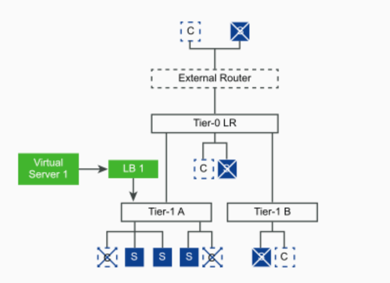
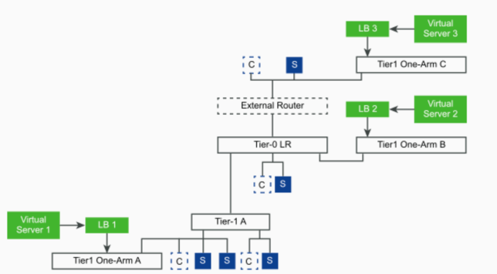
This is what every NSX-T load balancing blog article references that I could find at the time of writing. These are taken from the NSX-T documentation on docs.vmware.com.
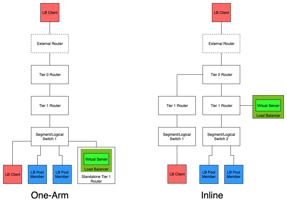
This is my interpretation of the stock diagrams. For me, this simplifies things and makes it clearer to understand.
One-Arm Configuration
For traditional load balancers this is usually the most simple setup but in the case of NSX-T it actually requires much more configuration. An NSX-T load balancer cannot be deployed on its own as it’s just a service. This service runs within the Service Router (SR) component of a Tier 1 gateway (the DR component of a Tier 1 handles the distributed routing function), therefore you need an edge device/cluster with a deployed Tier 1 to use load balancing.
Normally when you deploy a Tier 1 Router you link it to a Tier 0 to allow routing to and from the outside world as well as any other segments and Tier 1 routers in the environment. For a one-arm configuration you need to deploy a Tier 1 which is NOT connected to any Tier 0. In other words it is a standalone Tier 1 router. This allows the stand alone Tier 1 to be connected to the same network segment (in the same subnet) as the pool machines you wish to balance connections to whilst deferring routing to an existing Tier 1 router (connected to the same segment) that in turn is connected to Tier 0.
Traffic can still freely route in and out of the network segment without going through the load balancer if desired as it is not in the direct data path. SNAT ensures that incoming traffic directed to the load balancer is routed back out the same way for pool members. Lets set this up!
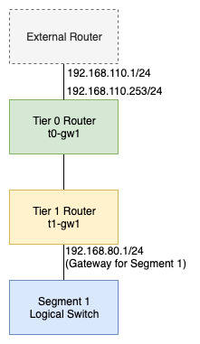
My starting configuration has a segment/logical switch named “Segment1” connected to a Tier 1 gateway called “t1-gw1” using a subnet defined as 192.168.80.1/24. This Tier 1 is advertising all routes for connected segments, vips etc. and gives basic networking capabilities for any machine connected to the segment. Anything I deploy onto “Segment1” can route out onto the external network (BGP config in place on “to-gw1”).
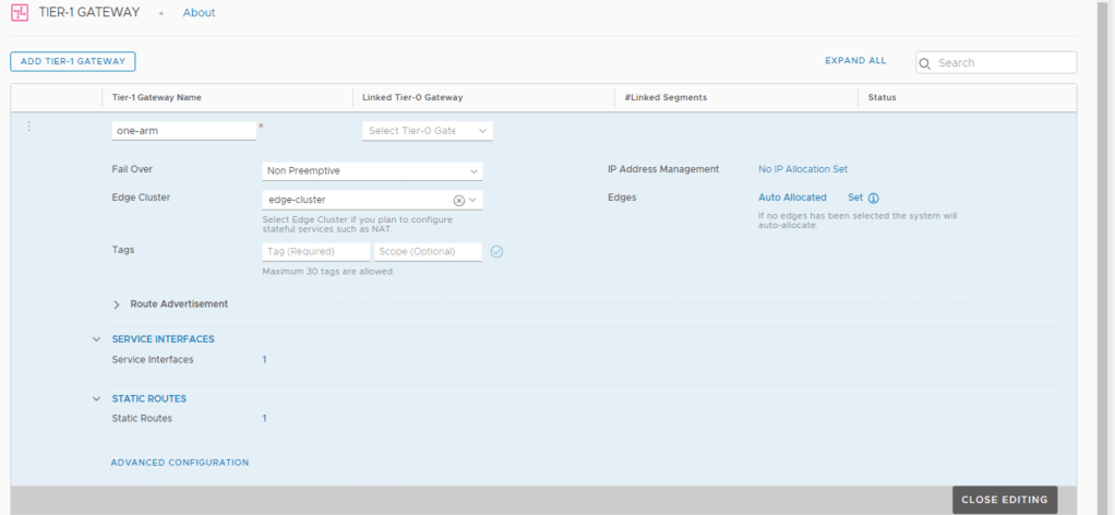
To deploy a one-arm load balancer I am first going to deploy a new Tier 1 (called “one-arm”) which looks like this. Notice the Tier 0 is NOT populated.

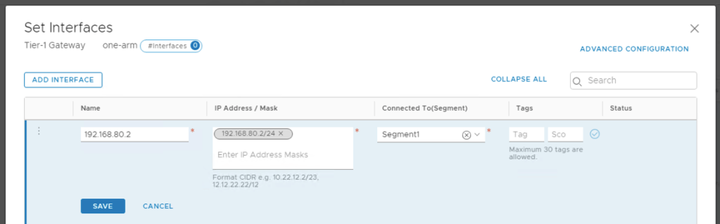
The standalone Tier 1 (“one-arm”) now needs to be connected to my segment “Segment1”. This would normally be done by defining an uplink type and subnet on “Segment1” however it is already configured with a connection to “t1-gw1” and we aren’t really after an “uplink”. To make this work you need to define a “Service Interface” on “one-arm” which connects to “Segment1”.
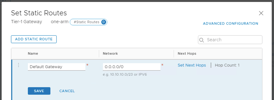
At this point my Tier 1 “one-arm” has an interface in “Segment1” but it can’t route out of the segment to reach other segments or the outside world. To fix this I need to add a default route on “one-arm” pointing to the gateway for the segment (which is 192.168.80.1 on “t1-gw1”). This is done by adding a static route to “one-arm”.
The “one-arm” Tier 1 now looks as follows, with one static route and one service interface.
At this point I can ping the service interface of “one-arm” from the external network as there is a route for the return traffic to follow. Now onto the load balancer.
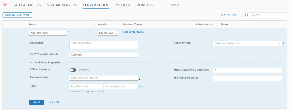
For this I am using a very basic configuration without any service monitors (I’m just proving the one-arm configuration). The first step is to create a Server Pool containing the IP addresses of one or more machines on “Segment1” that will be load balanced. One-arm requires SNAT to be used on the Server Pool to allow incoming traffic to the pool from the load balancer to also be returned via the load balancer. This is done by setting “Automap” as the SNAT Translation Mode (or defining an IP Pool for SNAT).

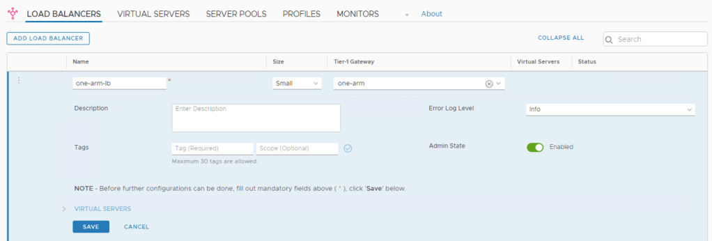
With the pool created I can then define the load balancer.
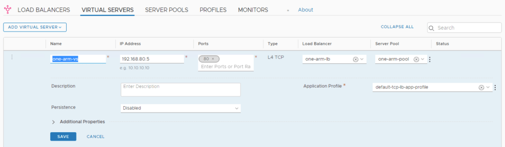
The final step is to then create a virtual server for the load balanced service and link it to the load balancer. The IP address needs to be in the same subnet as the pool members (in my example I am using 192.168.80.5 pointing to pool members 192.168.80.3 and 192.168.80.4).
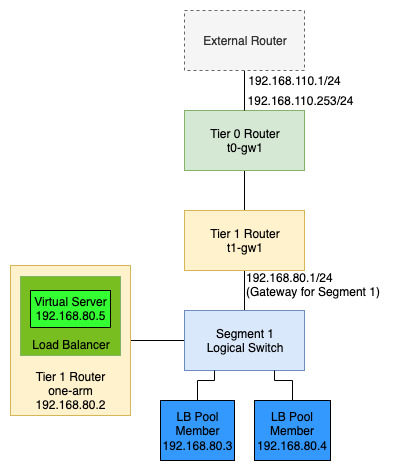
The final logical view now looks as follows.
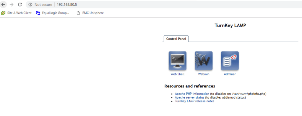
Hitting the virtual server IP address results in a successful connection to a pool member. In this case my pool members are just based on turnkey LAMP images (un-configured).
If you try disabling SNAT on the server pool you will see connectivity via the load balancer to the pool machines will fail.
In the next article (https://vnuggets.com/2019/09/16/nsx-t-inline-and-onearm-load-balancing-part2/) we will look at the inline implementation.

Pingback: NSX-T – Inline and One-Arm Load Balancing Part 2 | vnuggets