In part 1 of this mini-series I looked at how you implement a one-arm load balancing solution using NSX-T (https://vnuggets.com/2019/09/13/nsx-t-inline-and-onearm-load-balancing-part1/). In this second part I am going to switch focus to look at the inline implementation so you can see how the required components and configuration differs.
Logical Architecture
As a reminder from part 1, here is the logical architecture for an inline load balancing implementation with NSX-T (for a side by side architecture comparison view check out part 1).

Inline Configuration
The starting network configuration taken from the above diagram will be External -> T0 -> T1 -> Segment2. This is utilising the same routers as I did in part 1, this time with a new segment (“Segment2”) and associated subnet for the pool of load balanced machines to connect to.
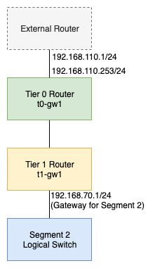
The key thing to understand with an inline configuration is that the load balancing interface (the Virtual Server IP) does NOT sit on the same network as the target machines that are being balanced across (i.e. the machines in the virtual server pool). The interface sits on a Loopback interface of the Tier 1 router as shown below.

In addition, client connections to the load balancer cannot come from the same network as the pool members. Only connections from other network segments (via the same or different Tier 1 routers) or from external sources are supported.
To start setting this up I don’t need to deploy any new Tier 1 routers as my basic Tier 1 “t1-gw1” already exists and provides routing for a number of other network segments. Instead I am going to define a Load Balancer on “t1-gw1”, adding the service to the existing configuration.
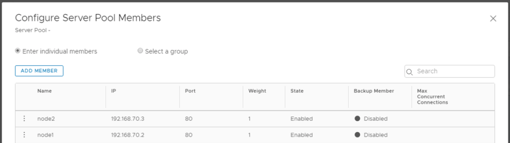
The first thing to setup is the pool (notice I am skipping profile and monitors here as this is a very simple example). As this an inline configuration the SNAT setting on the pool is set to “Disabled”.

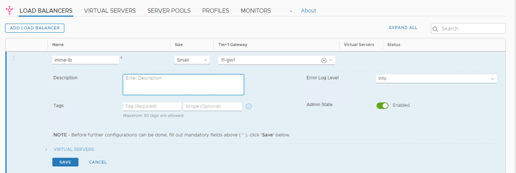
The Load Balancer service is then added to the existing Tier 1 gateway “t1-gw1” as follows.
Finally the Virtual Server is added and linked to the Load Balancer and Server Pool from the previous steps. The IP address used for the Virtual Server can be anything that does not clash with existing address/subnets advertised within the environment. Here I have used “192.168.10.200” which does not clash within anything else.

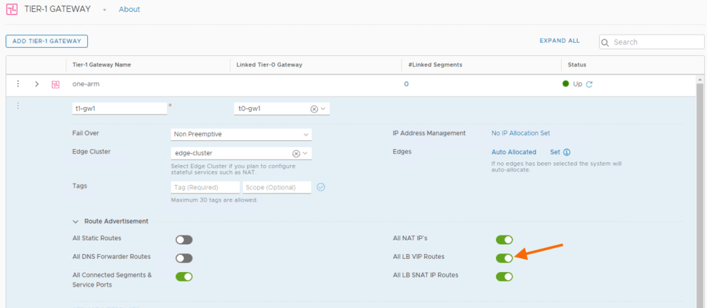
The Load Balancer and associated Virtual Server are now configured and should be serving traffic however it is always worth validating that your Tier 1 is configured to advertise Load Balanced VIPs.
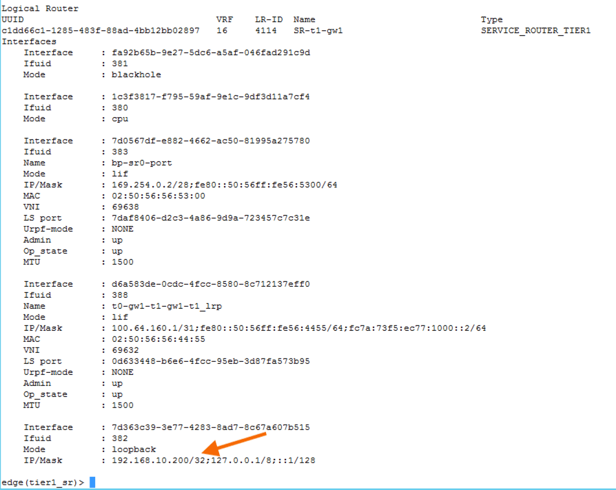
You can also check the configuration of the Tier 1 router from the command line by connecting to the edge node and selecting the Service Router for the Tier 1, in my case VRF 16.

Performing a “get interfaces” on this VRF brings back all the interconnect interfaces between Tier 0 and Tier 1 and SR/DRs as well as the loopback interface. Here you can see the IP address I assigned to my Virtual Server.
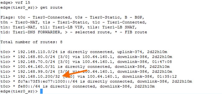
Changing to VRF 15 (the Service Router for Tier 0) should show me a route to my Virtual Server VIP.
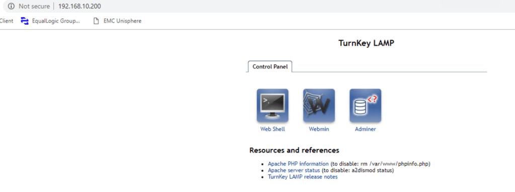
A quick test with a web browser to the virtual server address produces a successful connection to one of the machines in the virtual server pool.
Hopefully these 2 article have shown you how to get up and running with the two different load balancing methods.

Pingback: NSX-T – Inline and One-Arm Load Balancing Part 1 | vnuggets