Overview
Welcome to the fourth part of this series of articles covering Kubernetes and NSX-T. So far in this series I have deployed some hosts to be used for containers and Kubernetes with CentOS 7.6, prepped them for use, installed Docker and Kubernetes and created a Kubernetes cluster. In this part I am going to walk through the required NSX-T configuration (taking into account the architecture of my environment).
This series of articles includes:
- Part 1 – Deploying Container Hosts
- Part 2 – Deploying Docker & Kubernetes
- Part 3 – Creating a Kubernetes Cluster
- Part 4 – Configuring NSX-T Ready for NCP
- Part 5 – Deploying and Configuring NCP for NSX-T
- Part 6 – Testing the Platform
All of the configuration actions within this article are performed using the NSX-T policy interface rather than the “Advanced Network & Security” interface unless explicitly stated.
NSX-T Starting Configuration
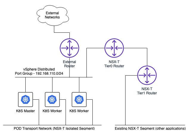
Before I start doing any new configuration within NSX-T I am going to give a brief synopsis of the environment as it stands.
- The second interface of each of my 3 CentOS VMs is attached to an isolated (i.e. not connected to any tier 1 router) NSX-T segment called “k8s-pod-transport”
- “k8s-pod-transport” uses a transport zone which is overlay based rather than VLAN based
- The second interface on each CentOS VM has no IP address assigned
- No other machines are attached to the “k8s-pod-transport” segment
- There is a Tier 0 router and Tier 1 router deployed (linked together) with BGP configured between tier 0 and an external upstream router which provides connectivity for existing services
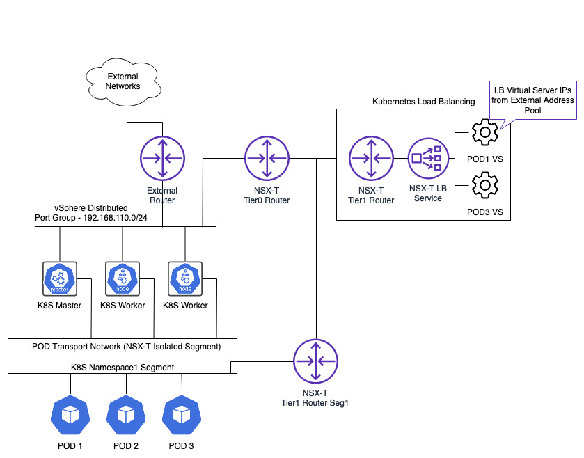
At the moment my network layout looks as follows.
Tagging
The first part of this setup is to make sure Kubernetes has a way to identify the switch ports that my 3 machines are using. This is so that container VIFs can be correctly created/linked against the right host VIFs. To do this the 3 host switch ports on “k8s-pod-transport” need to be tagged in NSX-T with the name of the Kubernetes node the port belongs to and the name of the Kubernetes cluster.
The node name for each server can be retrieved by running a “kubectl get nodes” command on the master. The node names should equal the hostnames.

The Kubernetes cluster name is arbitrary. As long as the name used in the tag matches the name provided in the NCP configuration file (I’ll cover this file in a future article) then all is good. Multiple Kubernetes clusters can use the same NSX-T deployment so the cluster tag allows each cluster to be differentiated from one another.
To assign the tags (each comprised of a scope and tag value) to the switch ports the segment needs to be edited and the segment ports selected.
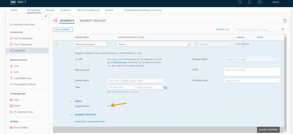
Each segment port is displayed. The port name helpfully includes the node name the port is connected to which allows me to easily identify I am assigning the right value on the correct port.

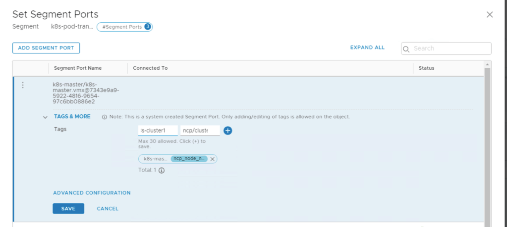
Editing each port in turn provides the ability to add one or more tags to the port. The following scope and tag values need to be applied (your tag values will most likely be different in your environment). Here I have decided that my Kubernetes cluster will be called “k8s-cluster1”.
| Scope | Tag Value |
|---|---|
| ncp/node_name | k8s-master |
| ncp/cluster | k8s-cluster1 |
IP Addressing
Kubernetes is divided into namespaces with each one able to contain multiple PODs (and one or more containers within each POD). Each namespace created in Kubernetes triggers a dedicated NSX-T segment (logical switch) to be spun up within NSX-T and therefore requires a network address and IP range to be assigned for the segment.
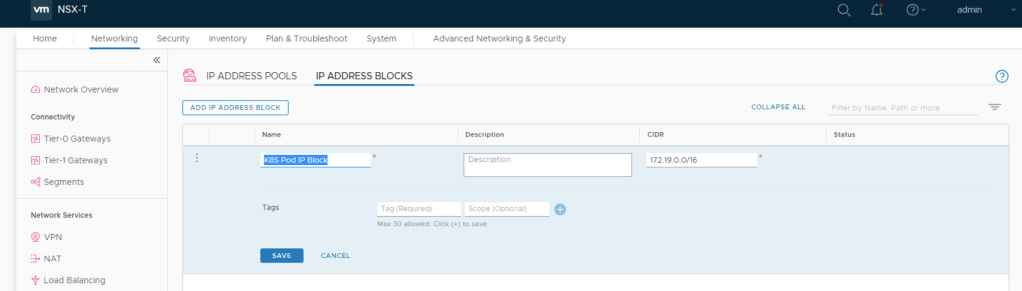
NSX-T needs to be setup with an IP Block (a sufficiently large enough CIDR) that can be divided down to provide a new subnet for each namespace that is created. Each POD created within a namespace will then automatically receive it’s IP address from the corresponding subnet.
I’m using “172.19.0.0/16” for the IP Address Block with the aim that each namespace will be assigned a /24 subnet from “172.19.0.0/16” (the subnet size for a namespace is defined within the NCP configuration file which I will cover in a future article). The net result of this will be each namespace created being able to hold 255 Kubernetes pods.
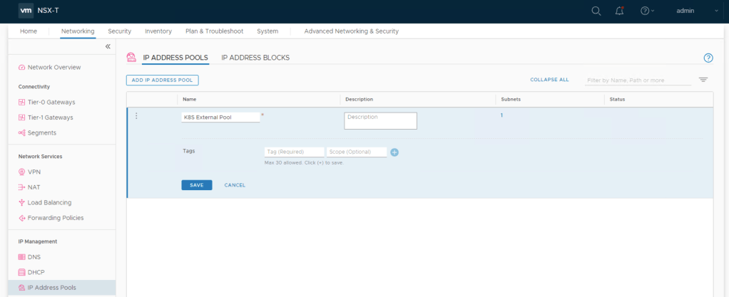
The next part of the IP addressing I need to do is for External Connectivity via load balanced services and is defined as an IP Pool rather than an address block. The Kubernetes cluster will create a dedicated Tier1 router including the load balancer service when NCP is configured. This load balancer will be able to be used by any PODs that have a load balanced configuration in their definition. Every load balancer virtual server created when a POD is deployed (if the POD defines one) will take an IP address from this “External Connectivity” pool and be added to the load balancer on this Tier1 router.
This is how the architecture looks with the load balancing added in.
Now I can create my external address pool. I am using a subnet defined with an IP range of 192.168.15.2 to 192.168.15.254.

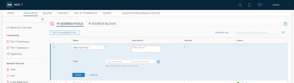
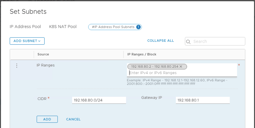
The same type of configuration (i.e. an IP Address Pool) is required for Network Address Translation (NAT) or in this case SNAT. Traffic leaving a POD and travelling through the NSX-T Tier 0 router has its source address translated to an address in this IP Address Pool.
For my configuration I am using 192.168.80.2 to 192.168.80.254.
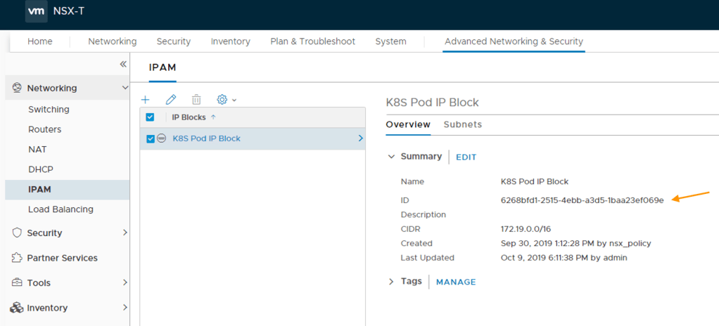
Object IDs
For the IP Block and 2 IP pools created, it is important that you make a note of their object ID’s for future use in the NCP configuration file. NCP 2.5.0 is supposed to accept object names rather than ID’s when populating the NCP file however through testing I have discovered that this is not the case (although referencing certain objects by name do work such as overlays, routers etc.). To obtain the block and pool object ID’s use the “Advanced Network & Security” view to locate each and take the ID from the overview tab.
Here I am fetching the object ID for my POD IP Block.
Firewall Sections
The last part of the NSX-T configuration is to tell NSX Manager where within the rule base to create any distributed firewall rules required for isolation and access. This is done by defining both a start and end section within the rule base which has to be done via the “Advanced System & Security” view rather than the policy view.
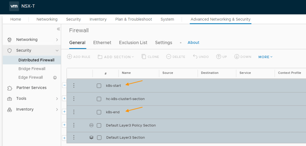
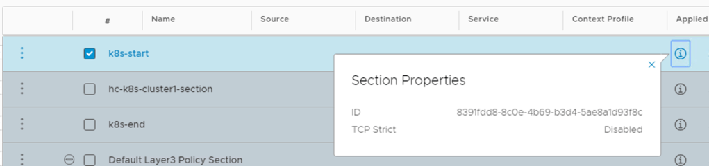
It’s important you take a note of the object ID for each section so that they can also be used in the NCP configuration file.
This completes my NSX-T configuration. In the next article I will be using the objects created (IP pools etc.) to help populate the NCP configuration file and deploy NCP to the Kubernetes cluster.

Pingback: Kubernetes and NSX-T – Part 3 Creating a Kubernetes Cluster | vnuggets
Pingback: Kubernetes and NSX-T – Part 2 Deploying Docker and Kubernetes | vnuggets
Pingback: Kubernetes and NSX-T – Part 1 Deploying Container Hosts | vnuggets
Pingback: Kubernetes and NSX-T – Part 5 Deploying and Configuring NCP for NSX-T | vnuggets
Pingback: Kubernetes and NSX-T – Part 6 Testing The Platform | vnuggets